2. SOURCES & DETECTORS

Radiation Sources
Until relatively recently, most spectrochemical measurements were made using incoherent sources, i.e., incandescent lamps, such as tungsten wire (filament) sources or discharge lamps such as the deuterium lamp. These sources are still widely used in many applications, such as UV-VIS spectrometers that do not require the features of laser emission: high irradiance, low divergence (little beam spreading with distance), near monochromaticity (limited wavelength rage), coherence (fixed phase relationship in emitted waves), and so on. The earliest lasers, such as the ruby or noble gas ion laser, operated at a small number of resonant frequencies (wavelengths). The development of tunable lasers has made lasers useful in a broad range of spectrochemical measurements.
Lasing occurs in a medium when four conditions are met: 1) the medium must support a population inversion, in which the number of excited states exceeds the number of lower energy states (once the inversion is achieved, it is called an active medium); 2) an effective pumping mechanism is needed to generate the population inversion in a ground state medium; 3) the active medium must be placed in a resonant cavity capable of amplifying the photons by stimulated emission and 4) the number of photons produced by stimulated emission must exceed the number lost by absorption and scattering. Stimulated emission occurs when a photon of the appropriate frequency 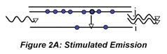 (ΔEmedium=hν) encounters an excited species in the active medium (lasing medium), which will emit a second photon of the same energy and phase, traveling in the same direction as the first photon, relaxing the medium to a lower energy level. When a medium is at thermal equilibrium, the number of lower energy states in the medium must outnumber the number of excited states. Many external energy sources, including electrical discharges, electrical currents or photon irradiation. can provide a pumping mechanism.
 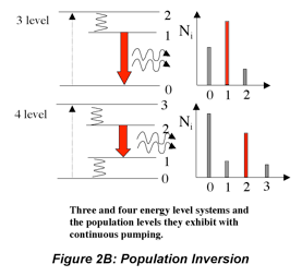 Only media that have more than two energy levels near the lasing transition can support a population inversion. Fig. 2B shows energy level diagrams representing active media that have three and four energy levels involved in lasing. Fig. 2B also shows the relative occupation of the energy levels with constant pumping. Note that in the three level system, lasing depletes the population inversion, but in four level systems a constant population inversion can develop. When the active lasing medium is p
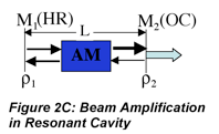 laced in a resonant cavity (a pair of mirrors at a distance that will support constructive interference in traveling waves), the amplifying medium becomes an oscillator that can produce emission. The high reflector has a reflectivity as close to 1 as possible. The other mirror, the output coupler (OC), is partially transmissive, so a fraction of the radiation generated in the cavity exits as a beam. Lasing is sustained in the medium when amplification by stimulated emission (generated during beam passes through the medium) exceeds absorption and reflection losses in the medium and at the mirrors.
We can go beyond the qualitative description above to write formulas that identify the impact of the various factors that influence laser performance. The increase in radiant flux as the beam passes through the medium is the opposite of the decrease we observe in absorption measurements. Using Beer’s law as an analogy we can write the following expression to describe the amplification by stimulated emission that occurs as the beam makes a round trip in the cavity and encounters the output coupler:
(2.1)
where l is the round trip cavity absorption and scattering loss, ρ1 and ρ2 are reflectances of the resonant cavity mirrors, E0 is the incident irradiance, σSE is the stimulated emission cross-section, Nj and Ni are the number of excited and lower energy state species, respectively, and l is the active medium length. Notice that the exponent is positive in this case. This beam amplification is often called ‘gain’ to reflect the increase in the beam amplitude. Unfortunately, there are at least two definitions of gain used by different communities of scientists. One, γ in m-1, refers to the increase reflected in the argument of the exponential, the other, G which is unitless, refers to the irradiance ratio (before and after amplification).

The difference in the number of excited and lower energy species in the medium is a measure of the population inversion. Ignoring absorption and scattering losses, the threshold population inversion (the point where gain just matches losses) can be computed from the mirror reflectivities, medium length and stimulated emission cross-section:
If you take the energy level diagrams with discrete energy levels depicted in Figure 2B literally, it may strike you as strange that the gain, γ, and stimulated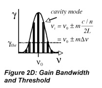 emission coefficient, σSE, are frequency dependent. Remember that even gas molecules are homogeneously and inhomogeneously broadened at temperatures above the cryogenic. Therefore the gain profile and stimulated emission cross-section have finite widths in frequency units. One consequence of this broadened transition is that there are usually a number of longitudinal modes (standing light waves that set up in the cavity) along the length of the cavity that have frequencies within the gain bandwidth over the threshold. The frequencies of these modes
 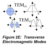 are separated by
  where L is the cavity (as opposed to medium) length (as usual c and n are the speed of light and refractive index). We can use optics, such as etalons, if we really need to isolate a single frequency. Similarly, laser emission travels across the width of the resonant cavity in a number of transverse (electromagnetic) modes that are designated by the number of nodes in the amplitude in the x and y directions. The fundamental mode, TEM00, has a nodeless gaussian profile in both the x and y directions as Fig. 2E shows.
So far, this discussion could give the impression that once a population inversion is achieved and lasing is initiated, it continues as long as the pumping mechanism is not interrupted. This depends entirely on the system. Lasers that have a constant output with respect to time are called continuous wave (CW) lasers. He:Ne (helium:neon, λ~633 nm) and ion lasers (Ar+, λ~488,5 514 nm; Kr+ λ~568 nm) are typically operated in this mode. The output of pulsed lasers varies periodically with respect to time. Pulsed lasers are very useful for conducting kinetic measurements or using time-dependence as a selectivity enhancement or noise discriminator. Many 3-level laser systems operate in the pulsed mode because lasing depletes the population inversion faster than the pumping mechanism can replenish it. For many systems, the pulse duration is approximately twice the cavity lifetime, which is the ratio of the roundtrip time for a photon in the cavity and the power loss during that round trip. Ignoring absorption and scattering losses, the cavity lifetime is

There are a number of different operational modes for pulsed lasers. The peak power of Q-switched lasers is much larger than that of normal pulsed lasers because an electrooptic modulator (essentially a fast shutter) temporarily blocks the high reflector so that the population inversion grows substantially above the threshold value. When the modulator opens and lasing is initiated, a very large pulse exits the cavity. Mode-locked lasers produce pulse trains of very narrow (< ps) pulses by forcing all the longitudinal cavity modes to oscillate in phase. This is accomplished by putting a modulator that has its oscillation frequency set to the reciprocal of the time it takes a photon to make a round trip across the laser cavity (this is much faster than the modulator in the Q-switched laser). In this case the pulse duration is given by

where γ is the gain threshold, l is the active medium length (rather than the cavity length L), Δν is the laser linewidth (in Hz) and mAOM and fAOM are the modulation depth and frequency applied to the beam by the acousto-optic modulator. One important consequence of the narrowness of mode-locked pulses is the broadening of the frequency bandwidth. There is an uncertainty principle at work, so the product of the bandwidth and pulse duration is fixed. The value of the product depends on the shape of the laser pulse; for Gaussian pulses, ΔνΔt=0.441.
Laser pulse properties can be manipulated to meet the requirements of measurements or experiments. Cavity-dumpers reduce the repetition rate of pulsed lasers by periodically deflecting the transmission of selected pulses. Cavity dumpers generally are based on electro- or acousto-optical devices. A variety of optical devices, including a prism pair, volume Bragg grating or optical fiber, can be used to reduce the duration (compress) laser pulses. Laser pulse power can be amplified by stimulated emission in another active medium or by interaction with a crystal or fiber that has a large nonlinear susceptibility. This will be discussed further in the last paragraph of this section. Of course, the average power of a pulsed beam is much lower than the pulse power because the duty cycle (fraction of time laser is emitting) of most lasers is small. For example, when a Q-switched CO2 (λ~10.6 μm) laser emits 1 mJ pulses in 1 msec, the peak power is 1W. If the pulse repetition rate (rate at which pulses exit the cavity) is 300 Hz, the average power is only 0.3W because the output is zero more than two-thirds of the time (700 of the 1000 msec in a second).
Until recently, the workhorse of laser spectroscopy has been the dye laser because the bandwidth of most organic dye spectra is around 50 - 100 nm, broad enough to provide limited tunability. Dye lasers have solutions of a fluorescent dye inside a resonant cavity that has the high reflector (non-transmissive mirror) replaced by a wavelength selection grating. The position of the high reflector grating determines which wavelength will exit the cavity. Flashlamps or single-wavelength pulsed lasers can be used to excite dye molecules into excited electronic and vibrational states. The molecules relax rapidly (in picoseconds) to the lowest vibrational level of the first excited state, which typically has a relatively long (1-10 ns) lifetime. Consequently, a population inversion can build up in the dye solution. More recently, vibronic lasers, especially the titanium:sapphire laser, have become important tunable laser sources for spectroscopic measurements. The energy levels of the titanium (III) ion doped into sapphire (Al2O3) crystals are such that excited electronic states of the ion can couple to the lattice vibrations of the crystal, forming a wide vibronic band in the ion ground state. The Ti:sapphire laser wavelength can be tuned from ~650 -1100 nm. Moreover, the Ti:sapphire laser can be mode-locked to produce ultrashort (<100 fs) pulses.
Another source of optical tuning is frequency mixing. We will discuss superposition waves and non-linear effects more thoroughly in the section on interference. For now it suffices to know that when two laser beams interact under the correct circumstances, they can combine to produce new beams that have different frequencies. When two laser beams of different frequencies, ν1 and ν2, are mixed in a non-linear crystal (one that has a large nonlinear susceptibility), such as β-phase barium borate (BBO), one of two new beams can be generated. The frequency of one beam is the sum (ν3 = ν1 + ν2) of the incident beams; the frequency of the other is the difference of the frequencies of the incident beam (ν3 = ν1 - ν2). Both of these phenomena require that the phases of the beams be matched (Δk=k3-(k1+k2)=0). Sum and difference frequency generation are used to extend the range of wavelengths available from tunable laser systems usually by mixing the tunable band, e.g. from a Ti:sapphire, with a beam from a monochromatic laser such as a Nd:YAG (λ~1064 nm). The frequency mixing principle is also used in optical parametric oscillators. These are coherent sources in which the optical gain comes from parametric amplification in non-linear materials rather than stimulated emission. In this case, the nonlinear crystal facilitates an exchange of energy from the pump beam to two beams. When the phase matching condition is met, the amplitude of the pump beam is depleted as the amplitude of the signal and idler beams increase. These sources are very widely tunable, so they are used for to generate difficult to access wavelengths, for example far infrared wavelengths for vibrational spectroscopy.
Radiation Detectors
For this discussion, radiation detectors are devices that convert radiant energy to electrical signals. A broad range of detector types is commercially available from photomultiplier tubes, which are vacuum tube technology, to semiconductors. Detectors are classified by various figures of merit that specify the devices’ performance. Among the most important classifiers are the responsitivity, R(λ), the ratio of the electrical output to the incident radiant power; the detectivity, D*, a measure how well the device measures small signals; the time constant, τ, a measure of the detector’s ability to respond to a sharply rising or falling optical signal; and the linear dynamic range, LDR, a measure of the range over which the plot of output vs. incident power is linear. The specific dectectivity is

where A is the detector area and Δf is the detector bandwidth. The bandwidth of a detector measures the breadth of the range signal frequencies to which the device responds. We will discuss noise and bandwidth in more detail after the discussion of Fourier transforms in Section 7. For now, remember that wide bandwidth detectors respond to incident light quickly. The time constant and rise time of a detector are both related to the bandwidth; they also measure how quickly the detector responds to changing signals, the time constant is given by

where fc is a ‘cut-off’ frequency, the frequency at which the responsivity falls to 0.707 times its maximum value. The rise time, the time it takes the detector response to reach 90% of its maximum value when a sharp input is applied, is proportional to the time constant. The ability of a detector to respond to low radiant power depends on its sensitivity and its dark current, which is the electrical output in the absence of light. The noise equivalent power, Φn, is the radiant power of an oscillating signal that produces an electrical signal with the same amplitude as a device’s dark current in a 1 Hz bandwidth.
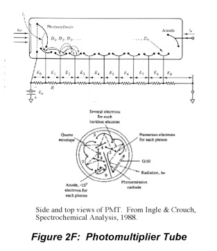

where η is the collection efficiency of the photoanode, G is the gain, R is the responsivity and Φ is the incident radiant power.
Semiconductor detectors do not generally have the range of features that PMTs have. They do not respond as deeply into the UV and they are generally several orders of magnitude less responsive. (There is usually no cascade or gain mechanism; the exception are avalanche phodiodes which are discussed briefly below.) However, they are rugged, linear, just as fast, have decent detectibility and are easily miniaturized. Consequently, they are used in many modern applications. A semiconductor detector is a diode, an electrical device with greater conductivity in one direction. Diodes are formed, for example, at the interface of silicon crystals doped with positive charge carriers (e.g., Ga) and negative charge carriers (e.g., As). When a negative potential is applied to the p-region and a positive potential to the n-region of the diode, a depletion layer forms at the pn junction. This is called reverse bias.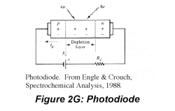 Photons incident on the depletion region generate electron/hole pairs, and thus, a current that is proportional to the incident power. Avalanche photodiodes (APDs) are becoming important photon detectors in spectrochemical analysis. A large reverse-bias accelerates the electrons produced by photon irradiation so that they collide with the semiconductor lattice producing a cascade of electrons for each photon detector. Although the gain produced by this mechanism is smaller than that observed in the PMT (G~103), the quantum efficiency of these devices is close to 90%. Moreover, they exhibit less noise, larger linear dynamic ranges and better electrical efficiency (less resistive heating) than PMTs. When these features and the compactness and flexibility of their packaging are considered, APDs can be better detection systems for many applications.
Multichannel detectors, which are used to measure images at several sample positions or spectra at several wavelengths simultaneously, are constructed from arrays of diodes or 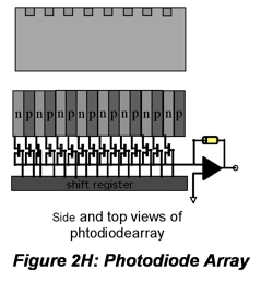 integrated circuits, such as semiconductor capacitors in charge transfer devices. Photodiode arrays are just what the name says: linear arrays of 25 μm photodiodes. What the name doesn’t reflect are the small storage capacitors connecting each diode to a shift register. In a measurement, the diodes are simultaneously irradiated, generating radiant flux dependent charge in each diode. This charge discharges the adjacent capacitor. The current required to recharge each capacitor and reestablish reverse bias in the adjacent diode is advanced to a preamplifier by a shift register and converted to voltage. Photodiode arrays are great for absorbance measurements because the sample and reference signals are typically both large. In this case, the large dark current (noise when detector is not illuminated) is less important. For other measurements, e.g. fluorescence or Raman, charge-coupled devices provide much better performance. CCDs are arrays of electrodes (metal oxide semiconductor capacitors) that store,
 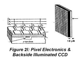 then measure the charge created in the depletion layer by photon irradiation. A single pixel consists of three electrodes (called gates) poised at low (ends) and high (middle) potentials so that the electrons generated by photon irradiation will be trapped under the middle gate. The charge is pushed to a shift register on the side of the chip by cycling the potentials on the electrodes so that the charge advances across the chip. The most responsive CCDs are constructed on substrate that is thinned (~10 μm) and backside illuminated (relative to electrodes). Quantum efficiencies >80% can be achieved for some wavelengths. Most importantly, the capacitor stores relatively large amounts of charge, so the LDR is wider and SNRs are larger than those of PDAs. One feature that PMTs have that CCDs lack is fast rise times. The fastest commercial chips acquire data at around 50 frames per second, which puts the rise time in the millisecond regime, compared nanosecond rise times in PMTs. Intensifiers, which act as fast shutters, are added to CCDs to address this limitation.
IR radiation is detected using thermal detectors because infrared photons are not energetic enough to produce current in PMTs or photodiodes. A number of IR detectors, including the Golay detector, thermocouple and bolometer have been described. The detector that often is used in FT-IR instruments is a pyroelectric detector that has a fast response time for detectors for this wavelength range, < 1 ms. The detector is made of triglycine sulfate (TGS), a material that develops a substantial surface charge when placed in an electric field. When IR radiation falls on the surface, the surface charge is disrupted and a current that is proportional to the derivative of the temperature change is produced. Hence, it is not useful for measuring constant radiation levels, but measures oscillating signals such as FTIR beams well. Semiconductor detectors also are available for the IR region. Single- and multichannel detectors based on HgCdTe (also abbreviated MCT) are commercially available.
(2.2)
(2.3)
(2.4)
(2.5)
(2.6)
(2.7)
(2.8)
(2.9)
(2.10)
(2.11)
Last Updated: 2/08/10