6. Interference & Diffraction

In many spectroscopic measurements, the incident, transmitted or emitted radiation beams are dispersed by frequency (or wavelength) to increase the selectivity and/or information content of the measurement. We’ve already seen why broadband light can be separated into its constituent frequencies using a prism, i.e., the dispersion (frequency dependence) of the refractive index. However, the use of diffraction or interference phenomena provides much better wavelength selection because these exploit the wave nature of light. Diffraction and interference are closely related phenomena; in fact, diffraction can be considered interference with scattering. So to understand diffraction, it is best to begin discussing interference.
Interference occurs when two beams are superimposed. The superposition principle states that constituent electric fields are additive:

Interference arises from the addition of the oscillations of at least two light beams that have similar wavelengths. This is illustrated in Fig. 6A for a pair of cosine waves of identical wavelength. The 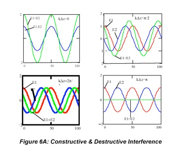 second wave (blue) is phase-shifted by 0o in the top left panel and 90o in the top right. In these pictures, the waves can have different z values (abscissa) at the same position on the graph. The frequencies of the beams are the same, but the beams are phase-shifted from one another because of the different distances (zi) traveled. The phase shift is kΔz.
Fig. 6A shows how two beams “interfere” with one another for several values of kΔz. For kΔz=0, the figure on the top left, the total electric field is twice that of the individual electric fields. This is constructive interference. As the phase shift increases to π/2 (90o), the figure on the top right, the composite electric field is less than twice the constituent fields and is phase-shifted from both of them. When kΔz= 2π/3 (120o), lower left figure, the composite electric field is only as large as the constituent fields and its phase is between the two. Finally, as the phase shift reaches one-half the wavelength, kΔz= π (180o) lower right figure, the amplitude of the composite electric field is zero. This last case is called destructive interference. A key point to understand is that two waves must have a well-defined phase relationship to give rise to interference effects. Waves with fixed phases are said to be “coherent”. The most common way of achieving coherence is to split a beam of incoherent light. This is counterintuitive, but is based on the idea that components of the wave will constructively interfere with each other when a beam is split and recombined. A second point to remember is that while electric fields are additive, irradiances are not. Consequently, the irradiance of a beam produced by destructive interference is small rather than precisely zero.
Several devices utilize interference to isolate or separate radiation by frequency. For example, interference filters are designed to pass a narrow wavelength range by having an optical cavity (in which interference occurs) built into them. The optical cavity is a thin dielectric film that 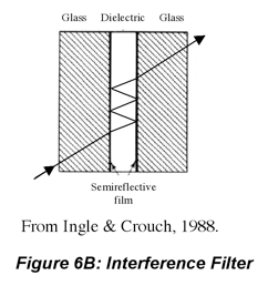 has pathlength d. The light is reflected from the boundaries on each side of the cavity, interfering with itself. The phase difference between the incoming beam and its reflected image is k(2dn) because the reflected beam travels the distance 2d in the cavity (assuming normal incidence, θ=0, even though θ>0 in the picture). Since k=2π/λ, when d=mλ/2, the phase difference between the incoming and reflected waves are k2d =2πm, leading to constructive interference. Here the integer m reflects the fact that all multiples of λ/2 are “modes” of the optical cavity and are transmitted. Thus, the transmitted wavelength becomes 2d(n2-sin2θ)1/2 =mλ, where m is an integer representing the order (or multiple) of the wavelength passed by the filter for any incident angle or dielectric. As a consequence of the interference laws, the interference filter will pass the most light at integer multiples of λ/2 and will pass the least amount of light at odd integer multiples of λ/4.
Interference filters are convenient when there is only one wavelength of interest. A common application of interference filters is in inexpensive optical instruments where the various emission lines of a mercury lamp are selected for absorbance or fluorescence measurements. Interference filters typically will select a wavelength within 1 to 10 nm, depending on the construction of the filter. The more selective filters have stronger reflections on either side of the cavity to enhance the interference by making the incoming and reflected electric fields closer to one another in amplitude. Holographic interference filters are devices that have many cavities evenly spaced at the λ/2 intervals. Holographic printing, which is produced by crossed laser beam etching, produces nearly perfect cavity spacing.
Fabry-Perot interferometers are devices that have adjustable cavity spacings so that the wavelength transmitted by the cavity may be scanned. (While there is some confusion around the nomenclature, Fabry-Perot etalons are interferometers in which cavity spacings are fixed. Their performance is similar that of interference filters, though the construction is different; for example, the dielectric is usually air.) An entire spectrum can be observed by varying (scanning) the cavity spacing of the interferometer. Unlike the interference filter, the cavity spacing of the Fabry-Perot interferometer is much larger than the wavelength of light. The optical wavelengths transmitted are thus very high order modes of the interferometer. The finesse, F, and coefficient of finesse, CF, which measure how selective an etalon or filter is for a particular wavelength, depend on the reflectivity of the cavity walls.

The bandwidth of the transmitted bands and resolving power of the cavity are related to F and CF. The full-width at half maximum (intensity) for transmitted bands and resolving power (ratio of the mean of two spectral bands that are separated by the device divided by the difference in their wavelengths) of an etalon (or interferometer position) are

These expressions imply that the bandwidth of transmitted bands decreases and separation between adjacent bands increases as the reflectivity of the cavity walls approaches unity. The amount of light transmitted by an interferometer is

where Φm is the maximum power in an individual fringe, k is the wavevector (see Section 1) and Δz is the difference in the optical pathlengths of adjacent beams leaving the device. In the interferometer (or etalon) Δz=2dcos(θ). (See text by Fig. 6B for definitions.)
The Michelson interferometer is a simpler device that utilizes the interference caused by a beam overlapping with a split and recombined version of itself to analyze the content of light sources. Beam splitters are integral components of most interferometers, so we will digress (a little) 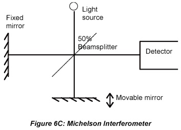 from devices based on interference briefly to describe them. The simplest beam splitter design is a partially silvered mirror. Aluminum vapor is deposited on the surface of glass so that a fraction of the light, for example 50%, is reflected while the rest is transmitted. Dichroic (two color) beamsplitters are designed to reflect one wavelength range and transmit another. For example, long pass beam splitters that reflect high energy photons are useful for separating fluorescence or Raman from scattered excitation beams. Dichroic beamsplitters are more expensive than absorption based filters (dyes trapped in glass) but more rugged because most of the incident radiation is either reflected or transmitted and cannot damage the optic. Actually, dichroic beamsplitters are interference-based devices. Alternating layers of optical coatings on glass substrates produce constructive interference of some wavelengths and destructive interference of others. Variations in the number, thickness and composition of these coatings produce many types of filters.
In the Michelson interferometer light is split at a 50% beamsplitter then recombined to produce interference. In the case of a monochromatic source, whenever the difference in the path lengths in the two arms is a multiple of the wavelength produced by the source, constructive interference occurs at the detector producing a large signal. When the path length is an odd multiple of one-half the wavelength, destructive interference occurs and the detector signal is small. Pulling the moving mirror at constant speed produces an oscillating signal (called an interferogram) whose frequency is depends on the frequency of the source radiation. In fact, the frequency of the interferometer signal is proportional to the speed of the moving mirror and inversely proportional to the wavelength of the radiation. Scanning (pulling/pushing) the movable mirror thus allows straightforward determination of the frequency of the source radiation. In a later section we will see that the spectrum of a polychromatic source can be obtained by Fourier transformation of the output of the Michelson interferometer.
Diffraction
For applications where wavelength tunability (rather than single wavelength dependence) is desired, other devices based on interference are employed. A common device is the diffraction grating, which produces interference by scattering radiation off evenly spaced scratches that have been etched on a flat surface. The electric field is scattered in all directions (away from the 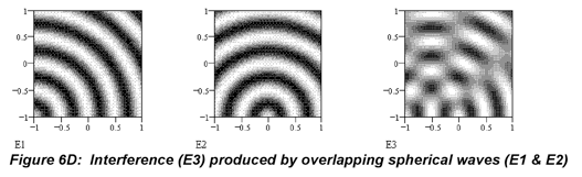 surface) when light strikes a scratch mark. The interference produced by combining the scattered fields is illustrated above, where contour plots of oscillating electric fields are shown. The electric field emanating from the point in the lower left hand corner (Fig. 6D-E1) is added to the electric field emanating from the lower middle of the surface (Fig. 6D- E2) to give the total electric field over the area (Fig. 6D- E3). The result, as Fig. 6D- E3 shows, is that the electric field will only propagate only at certain angles, an effect called diffraction. Diffraction is thus an interference effect in which radiation constructively interferes at particular angles. This angular dispersion physically resolves the components of pplychromatic radiation.
A diffraction grating has many evenly spaced scratches on the surface, but the basic principles are easiest to illustrate with just two scratch marks. Rather than using contour plots of the electric field (as above), it is simpler to draw lines representing the maximum electric field. The incident light (black) is parallel to the surface normal (α=0). The grating surface is perpendicular to the view below, above and below the plane of the page. Without the scratches, we’d see specular reflection off the surface. Because 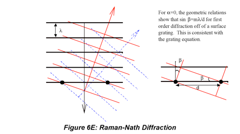 the scratches produce interference, the reflected beam (red) makes an angle, β, with the surface that depends on the groove (scratch) spacing, d and the wavelength of the radiation, λ. Diffraction from a surface grating gives multiple orders, m. The dashed blue ray is second order. This is the Raman-Nath diffraction limit illustrated in Fig. 6E.
Reflective diffraction gratings have been used for decades in optical spectrometers, but the problem of multiple orders decreases grating throughput. Blazing, where the scratches are etched at angles that push the reflectance into the first order, enhances the intensity in the first order. However, this requires advance choice of the wavelength region. Fig. 6F illustrates that volume gratings eliminate multiple order diffraction. They are made by holography, and their general appearance can be thought of as an interference filter rotated 90o (the rows of grooves etched in the device form optical cavities of sorts). (The gray dots show that the planes of volume gratings are similar to parallel stacks of surface scratches). Diffraction from a volume grating gives only first-order diffraction. Higher orders destructively interfere. This is the Bragg diffraction limit illustrated in 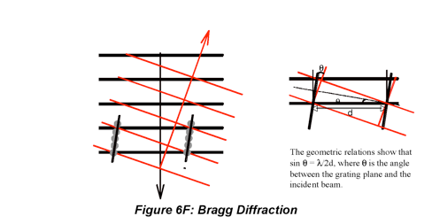 Fig. 6F. Given θ as the angle between the grating and the incident light, the figure illustrates the familiar Bragg equation, where sinθ = λ/2d. Holographic volume gratings have very high diffraction efficiencies (claimed to be close to 100%), with all of the light going into the first order, so spectrometers based on these devices have much higher throughputs than those based on reflective diffraction gratings. Volume gratings have been introduced to optical spectrometers for a number of years now. Commercial spectrometers based on such gratings are available.
A number of monochromator and spectrograph (exit aperture rather than exit slit) designs are used to incorporate diffraction gratings into the optical train of spectrometers. The Czernzy (pronounced Churny) -Turner is very commonly used design for reflective gratings, but the compactness of the Littrow design is convenient for many applications. The resolution of these devices depends on the slits and curved mirrors used to direct the light to and from the grating as well as the spacing of grooves on the grating, as the following equation shows

where Wslit is the slit width, f is the focal length of the curved mirror, d is the groove spacing and β is the angle at which the diffracted ray leaves the grating. The monochromator throughput,Υ(λ), also depends on these (and related) factors.
The etched surface diffraction grating and the holographic volume grating are permanent gratings. Useful transient gratings also can be written into materials. For example acousto-optic gratings may be written in quartz. Quartz is a piezo-electric material whose density, and thus refractive index, changes with applied voltage. A high frequency, i.e., RF, oscillating voltage induces an oscillating density gradient in the quartz. This grating will diffract radiation at the refractive index boundaries. The acousto-optic grating is transient because it disappears when the RF power is off. Ingle & Crouch discuss modulators, which modify beam power using this technology. A more recent development is their use as tunable Bragg diffraction gratings. The entire visible spectrum can be scanned in fractions of seconds by varying the RF frequency.
Interference
(6.1)
(6.2)
(6.3)
(6.4)
(6.5)
Last Updated: 3/17/10
