4. LIGHT AT INTERFACES

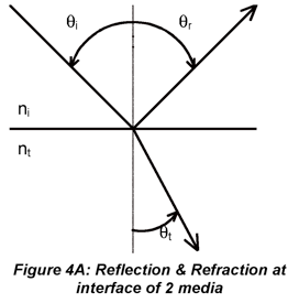
Fig. 4A illustrates what happens when electromagnetic radiation crosses a smooth interface into a dielectric medium that has a higher refractive index (nt>ni). We see two phenomena: reflection and refraction (a specific type of transmission). The angle of reflection, θr, equals the angle of incidence, θi, where each is defined with respect to the surface normal. The angle of refraction, θt, (t for transmitted) is described by Snell’s law (of Refraction):

The radiant power of the reflected and refracted light depend on several factors. The Fresnel equations describe the dependence of the reflected light on the angle of incidence, the refractive indices of the two media and, in some cases, the polarization of the incident beam. In the case of normal incidence, the reflectance (ρ=Er/E0) is

The reflectance is thus related to the difference in refractive indices between the two media. For glass and air, which have refractive indices of 1.50 and 1.00, respectively, the reflection coefficient is 0.04. For water and diamond, which has a refractive index of 2.4, the reflection coefficient is 0.08. It is therefore easier to see diamonds in water than it is to see glass in air.
At arbitrary incidence, the polarization of the reflected and or refracted beams may be impacted. This is described using Fresnel equations that refer to the reflection coefficient (related to beam amplitude) of polarized EMR beams rather than the reflectance (related to beam power). If the electric vector is oscillates in the plane of incidence (p-polarization), the reflection coefficient is denoted r||.

If the electric vector vibrates in the direction perpendicular to the plane of incidence (p-polarization), the reflection coefficient is

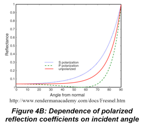

where (τ=Et/E0) as long as the absorbance(α=Ea/E0) is negligible.
Light at Interfaces
Polarizers
The simplest means of controlling the polarization of light beams is to use a Polaroid film (not photographic film), which transmits one polarization and absorbs the other. Polaroid films utilize the concept that molecules absorb light along one molecular axis. Strongly absorbing dyes are incorporated into a polymer e.g., polyethylene, film, which is then stretched to align the molecular axes to the stretch axis. The transmission axis of the film is perpendicular to the stretch axis. The polarization extinction coefficient, E||/E⊥, of a Polaroid can be as high as 103. Even high quality Polaroid film is inexpensive. There are two significant disadvantages of Polaroid films. First, even the transmitted polarization is strongly attenuated by the film. This can be appreciated by noticing that Polaroid sunglasses are dark. In a low intensity fluorescence or Raman measurement, a Polaroid film would reduce the signal dramatically. Second, Polaroid film is easily damaged by intense, e.g., laser, beams because of strong absorbance. More sophisticated means of controlling polarization are required for such demanding applications.
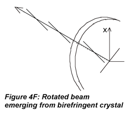
The plane of polarization of a source can be rotated to orient the electric field at an arbitrary angle. An obvious way to do this is to use a randomly polarized (unpolarized) source and rotate a Polaroid (film) in the beam. This is not widely used because of the disadvantages of Polaroids which have already been discussed, and often the light, e.g. from lasers, is already polarized. To rotate the plane of polarization of polarized sources, birefringent crystals are usually used. A device called a “half-wave” plate or retarder is used to rotate plane-polarized light through a 180o phase angle; this device can maintain very high polarization extinction. Half-wave plates utilize three concepts. First, the superposition principle (more on this in the section on gratings) states that electric fields are additive. Second, in a birefringent crystal, the two polarization components of the incident beam will experience different refractive indices (provided that the beam is not propagating along the crystal’s optic axis) and different phase changes as they go through the crystal. Third, the crystal faces are cut parallel to the optic axis so the fast axis (lower n, no in positive uniaxial crystals such as quartz) and slow axis (higher n) are perpendicular and the crystal width can impose the largest possible phase shift for the crystal material.
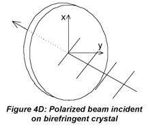
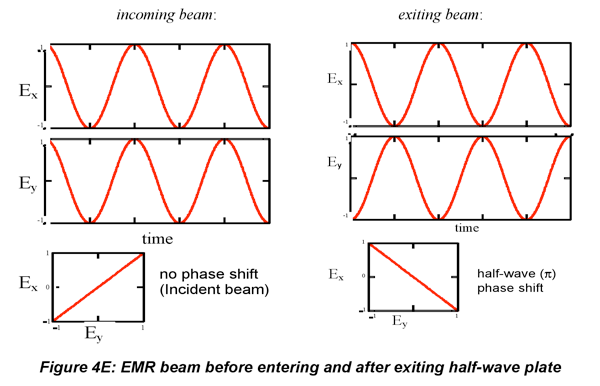
When the beam transits the birefringent crystal (not along optic axis), the x- and y-components experience different refractive indices and exit the crystal phase-shifted relative to one another. A half-wave plate is a crystal whose thickness is chosen, based on its refractive indices, to phase-shift one component relative to the other by 180 (1/2*2π radians, hence the name half-wave plate). The components of the E field become

Circularly polarized light also can be generated from linearly polarized light by phase-shifting the x- and y-components relative to one another. Here a “quarter-wave” (90o, π/2 shift) plate is used. After passage through the material, the electric fields are the following.


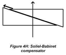
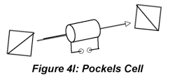
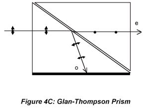
Polarized light can be analyzed (as opposed to generated) using a second polarizer, e.g., Polaroid film or Glan-Thompson prism, to select Ex or Ey for measurement. For linearly polarized light, the irradiance passed by the analyzer grows more or less intense as the analyzer is rotated and the transmission axis of the analyzer moves toward and then away from the polarization axis of the beam. In fact, E(θ)=E (0)cos2θ where θ is the angle between the analyzer transmission axis and the polarization axis of the radiation. Techniically, this procedure is not applicable to circularly polarized light because the analyzer allows the investigator to measure the amplitude of polarization components in various directions. Circularly polarized light is indistinguishable from randomly polarized light because the amplitude of the transmitted component doesn’t change as the analyzer is rotated. However, in the context of a measurement, when Ex= Ey, after linearly polarized light is passed through a quarter-wave plate, it can be surmised that the light is circularly rather than randomly polarized. If the phase-shift must be known, then the Soliel-Babinet compensator or Pockels cell can be used to determine the phase shift needed to bring the polarization back to linear. This is sometimes necessary for measurments where the phase shift must be determined experimentally. For most purposes, the Polaroid or Glan-Thompson analyzer is sufficient.
(4.1)
(4.2)
(4.3)
(4.4)
(4.5)
(4.6)
(4.7)
Last Updated: 2/08/10
