The simplest means of controlling the polarization of light beams is to use a Polaroid film (not photographic film), which transmits one polarization and absorbs the other. Polaroid films utilize the concept that molecules absorb light along one molecular axis. Strongly absorbing dyes are incorporated into a polymer e.g., polyethylene, film, which is then stretched to align the molecular axes to the stretch axis. The transmission axis of the film is perpendicular to the stretch axis. The polarization extinction coefficient, E||/E⊥, of a Polaroid can be as high as 103. Even high quality Polaroid film is inexpensive. There are two significant disadvantages of Polaroid films. First, even the transmitted polarization is strongly attenuated by the film. This can be appreciated by noticing that Polaroid sunglasses are dark. In a low intensity fluorescence or Raman measurement, a Polaroid film would reduce the signal dramatically. Second, Polaroid film is easily damaged by intense, e.g., laser, beams because of strong absorbance. More sophisticated means of controlling polarization are required for such demanding applications.
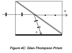
A more transmissive device that is used to create highly polarized light is the Glan-Thompson prism. Its geometry is illustrated in Fig. 4C. It is constructed using two
birefringent prisms. A birefringent material is asymmetric on the molecular scale and thus optically anisotropic. Birefringent crystals such as calcite (CaCO
3) and quartz can divide monochromatic incident beams into two beams that have orthogonal polarizations because the components of incident light traveling along most crystal directions experience two different refractive indices. The refractive index for one polarization (ordinary rays), n
o, obeys Snell’s law and the other polarization (extraordinary rays), n
e, doesn’t. However, these crystals have an optic axis along which components of the electric field travel at the same speed regardless of the their polarization. The optic axis of the crystals in Fig. 4C is perpendicular to the plane of the page. The Glan-Thompson prisms are cut so that the light component experiencing n
o (1.6584 for calcite) is totally internally reflected, while the component experiencing n
e (n
e=1.4864) is transmitted. Cementing the first crystal section to a second allows the n
e component to propagate essentially undeviated. (Remember the light bends on entering a new medium, so gluing the crystals enables the device to accept light from a wider field of view.) Polarization extinctions on the order of 10
4 to 10
5 are achieved with high transmission. Most vendors use a glue that matches the index of refraction between the two crystals so that there is even less deviation of the beam. For applications to high-powered lasers, air is left in the space between the two crystals, (the polarizer is technically called Glan-Foucault in this case) and the crystals are cemented into a tubular holder to keep them in place. These devices have a narrower field of view than the Glan-Thompson configuration.
The plane of polarization of a source can be rotated to orient the electric field at an arbitrary angle. An obvious way to do this is to use a randomly polarized (unpolarized) source and rotate a Polaroid (film) in the beam. This is not widely used because of the disadvantages of Polaroids which have already been discussed, and often the light, e.g. from lasers, is already polarized. To rotate the plane of polarization of polarized sources, birefringent crystals are usually used. A device called a “half-wave” plate or retarder is used to rotate plane-polarized light through a 180o phase angle; this device can maintain very high polarization extinction. Half-wave plates utilize three concepts. First, the superposition principle (more on this in the section on gratings) states that electric fields are additive. Second, in a birefringent crystal, the two polarization components of the incident beam will experience different refractive indices (provided that the beam is not propagating along the crystal’s optic axis) and different phase changes as they go through the crystal. Third, the crystal faces are cut parallel to the optic axis so the fast axis (lower n, no in positive uniaxial crystals such as quartz) and slow axis (higher n) are perpendicular and the crystal width can impose the largest possible phase shift for the crystal material.
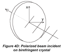
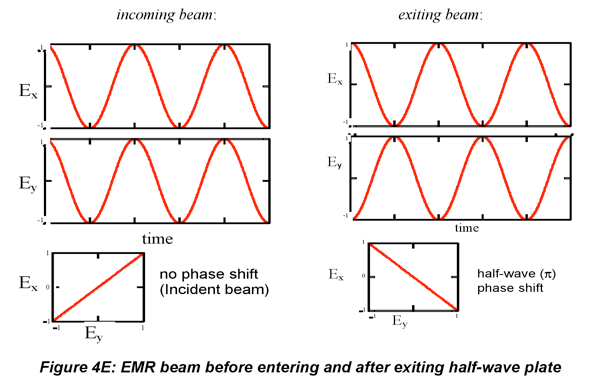
Consider a beam with its polarization axis exactly halfway between the two (x and y) crystal
axes incident upon a birefringent crystal, as illustrated in Fig. 4D. For the incident beam, the x- and y-components of the electric field have the same amplitude: E
0/2cos((t -n
airz/c)). Spatially, the x- and y-components are in-phase with one another (go through zero and crest at the same points along z). The graph at the left of Fig. 4E shows the electric vectors resulting from the two components, which have the initial plane of polarization of 45
o. The total electric field oscillates at a 45
o angle between the x and y axes.
When the beam transits the birefringent crystal (not along optic axis), the x- and y-components experience different refractive indices and exit the crystal phase-shifted relative to one another. A half-wave plate is a crystal whose thickness is chosen, based on its refractive indices, to phase-shift one component relative to the other by 180 (1/2*2π radians, hence the name half-wave plate). The components of the E field become
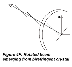
The graph on the right of Fig. 4E shows how the orientation of the electric field has rotated to the perpendicular direction A view of the emerging beam, in three dimensions is shown on the right (Fig. 4F). In summary, the key
to rotating the plane of polarization to the perpendicular direction is that the half-wave plate 1) imparts exactly a 180
o phase shift and 2) preserves the amplitudes of the x- and y- components (E
0/2). If either factor is missing, the resulting polarization will not be perpendicular to the original polarization. It is also clear that retarders are cut for a particular wavelength because n
x and n
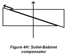
y are wavelength-dependent. A retarder can be made to polarize wavelengths close to the one for which it was cut by rotating the plate around its vertical axis to increase the width of the glass, but this solution has limited applicability. Mica is an inexpensive birefringent material that works well but is somewhat fragile. Quartz is more long-lived but is more expensive. Quartz also has a stronger wavelength dependence than mica. So mica is the choice if the wavelength is to be varied. Later, we will see that a Soliel-Babinet compensator allows indefinitely broadband operation.
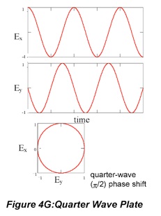
Circularly polarized light also can be generated from linearly polarized light by phase-shifting the x- and y-components relative to one another. Here a “quarter-wave” (90o, π/2 shift) plate is used. After passage through the material, the electric fields are the following.
Plots of E
x vs. E
y given at left illustrate that circularly polarized light has a large amplitude electric field, but a plane of polarization that rotates in a circular fashion about the axis of propagation as a function of time. If the y-component is shifted by +π/2, then right-handed circularly polarized light is generated, if the phase shift is -π/2, then left-handed circularly polarized light is generated.
The right-hand rule is used to assign a handedness to circularly polarized light. Pointing the thumb in the direction of propagation, the fingers point to in direction of rotation of the electric field. If the phase shift of the wave-plate is not exactly 90
o, the magnitude of the electric field changes with angle. Elliptically polarized light traces out an ellipse rather than a circle or a line. Elliptically polarized light can also be generated (accidentally) if the incoming electric field does not have equal x and y components even if the phase shift is exactly 90
o. To generate circularly polarized light in the lab, quartz or mica qu
arter-wave plates are typically used, with the thickness cut for a particular wavelength as in the case of half-wave plates. For a laboratory in which broadband control of polarization is required, a Soliel-Babinet compensator can be used. This device consists of a pair of wedges that allows the thickness of the retarder to be varied, as illustrated in Fig. 4H. (Consider this a top view.) The compensator has a fast and slow axis as any retarder would. The phase-shift can be arbitrarily varied to generate either linearly or circularly polarized light over the range of the compensator.
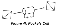
Another way of imposing broadband polarization control is to use a device called a Pockels cell. This device is based on a crystal that is isotropic until a voltage is applied across it.
When a voltage is applied across the crystal, a birefringence, that is difference in n
e and n
o develops. The relative values of n
e and n
o can be controlled electronically in the lab with high accuracy. The additional advantage is that the Pockels cell allows control of polarization by a computer for measurement automation. When this device is mounted between crossed polarizers, it becomes a useful source modulator: no light is observed when V
applied = 0, but is transmitted when a voltage is applied.
Polarized light can be analyzed (as opposed to generated) using a second polarizer, e.g., Polaroid film or Glan-Thompson prism, to select Ex or Ey for measurement. For linearly polarized light, the irradiance passed by the analyzer grows more or less intense as the analyzer is rotated and the transmission axis of the analyzer moves toward and then away from the polarization axis of the beam. In fact, E(θ)=E (0)cos2θ where θ is the angle between the analyzer transmission axis and the polarization axis of the radiation. Techniically, this procedure is not applicable to circularly polarized light because the analyzer allows the investigator to measure the amplitude of polarization components in various directions. Circularly polarized light is indistinguishable from randomly polarized light because the amplitude of the transmitted component doesn’t change as the analyzer is rotated. However, in the context of a measurement, when Ex= Ey, after linearly polarized light is passed through a quarter-wave plate, it can be surmised that the light is circularly rather than randomly polarized. If the phase-shift must be known, then the Soliel-Babinet compensator or Pockels cell can be used to determine the phase shift needed to bring the polarization back to linear. This is sometimes necessary for measurments where the phase shift must be determined experimentally. For most purposes, the Polaroid or Glan-Thompson analyzer is sufficient.