We have installed but not fully characterized experimentally an external ion source, injection lens and design TOF selector on Finnigan FT MS 2000 instrument. Design and simulation considerations are presented in this poster. Physical aspects of unique problem of interfacing a highly collimated, elongated ion beam ion injection system (Z-axis beam path of 1400 mm) with a high magnetic field (3 Tesla) instrument along with TOF ion selection with a non-linear electrostatic potential distribution along the beam path (0 to 1500V) are discussed.
Our prototype version of the Finnigan FTMS 2000 External Ion Source (EIS) and its
performance characteristics were presented at the last ASMS conference. Simulation results
obtained using SIMION 6.0 interface have precisely matched experimental operating conditions
for the best performance in CI CID experiments. Since then a more rigorous modeling of the
magnetic field has been implemented into a fully operational dynamic FTMS 2000 computer
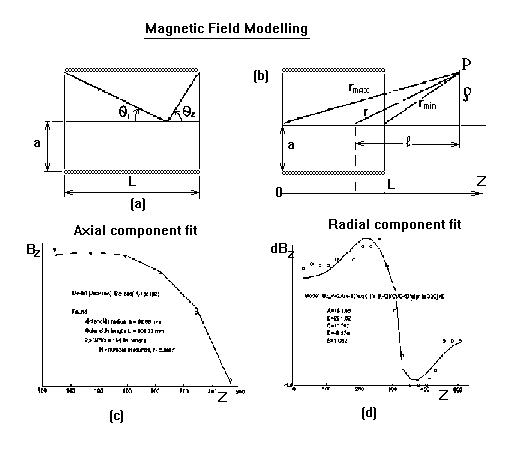
model realized using SIMION 6.0, Fig 1. Specifically, the magnetic field has been modeled fitting
geometry and current parameters in equations for resistive solenoids using actual
measurements of the Bz. Summary is of the modeling is shown in Fig below

Recently designed CI/EI ion source assembly with
an intermediate Einzel lens were incorporated with the model (shown in Fig
below):

External Ion Source acceleration - deceleration unit with optimized potentials on the electrode
plates is shown schematically in Figure below (upper part; source block
is on the right; Z-X scaling factor
changes from 1:1 to 1:10 at the position of the first acceleration lens). It has 14 acceleration
cylindrical (45 mm long with 45 mm diameter) electrodes.
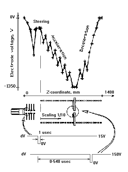
The last acceleration element serves as a 3.5 mm diameter conductance limit for the ion beam. It opens into the deceleration part of the unit, which brings the potential along the beam path back to 0 volts in the vicinity of the ICR cell. Beam focusing is assisted by altering the sign of potential gradient along the Z-coordinate. The system has been redesigned this year to incorporate the least number of adjustable voltages without losing beam focusing properties. There are only two control voltages applied to the acceleration-deceleration unit itself - namely, the conductance limit and the first acceleration lens assembly. In SID experiments collision energy is controlled by floating the source block where the ion beam is initially created. Extraction lens and Einzel lens elements following the source block cone are separately controlled.
TOF ion selection is generally useful in FTMS because of dynamic range and ion storage limitations. The elimination of matrix ions, selection of charge state ion groups, etc., prior to initiating characteristic ICR measurements is a desirable goal. It is crucial in variable energy SID experiments.
Time of flight between any two point z1 and z2 along the straight Z-axis ion trajectory can be
analytically found from the basic equation:
t=int_t1^t2(sqrt(m*dx/(2(Ek-V(z)))))
where m is the ions mass, Ek is the starting energy and V(z) is the z-axis potential. Figure 1
shows the potential distribution along the flight tube, under conditions
which for the ion beam focusing is optimized. Even such a complex potential distribution can be
interpolated with polynomials and Equation above can be solved
analytically. A simpler approach is to
solve the Eqation for ion velocities and TOF at any point for any given
potential array geometry
numerically. Fig below shows the interactive output of this program
(written in MATLAB 4.2).
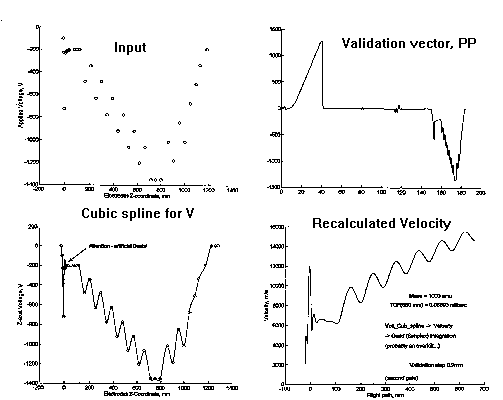
Certain precautions must be taken, as usual, when fitting potentials with high-order polynomials meaning that one must always check for the absence of artificial beats in the validated voltage distribution (Fig.(c)). This approach is much faster then SIMION itterative MD modeling, moreover the problem of refinement of large potential arrays (i.e. the unit cell constant limitation to the precision) does not arise. However SIMION 6.0 remains the most powerful and versatile tool which can be used to confirm the MATLAB program results.
TOF mass selection is implemented using as ion gates two deflection plates pairs (Fig 4) along the ion trajectory and operate them in such manner that deflection is always active accept for the two short pulses with an adjustable time duration between them.. Design questions we have addressed include the following:
The ratio of the times which it takes for an ion to reach the gate and to pass though it obviously depends on potential along the path rather then mass. However the gate-passing time is itself as important for the normal operation of the gate as the open-gate pulse width. Some illustrations from our theoretical study of non-linear field TOF are given in the Results section. Briefly, the transmission function and resolution of the selector with the two gate-deflector plates pairs are optimized by choosing the deflector plate lengths such that the two gate-passing times are equal. In the chosen setup the estimated ion-presence-at-the-gate ratio for gates 1 and 2 was about 1:10. Rough approximation of locally constant velocities suggested 1:10 gate length ratio. Taking nonlinear field into consideration changes the packet form but does not greatly effect the resolution order.
The lag between the two gate-open pulses is readily calculated using the above approach for each mass to be selected.
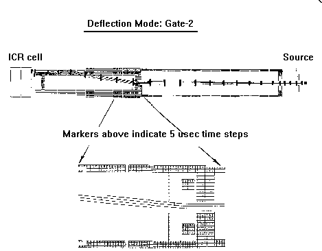
Figure below shows normal operation mode of our FTMS 2000 model. Two pairs of deflectors appointed with arrows were both used as gate 2 for performance comparison.
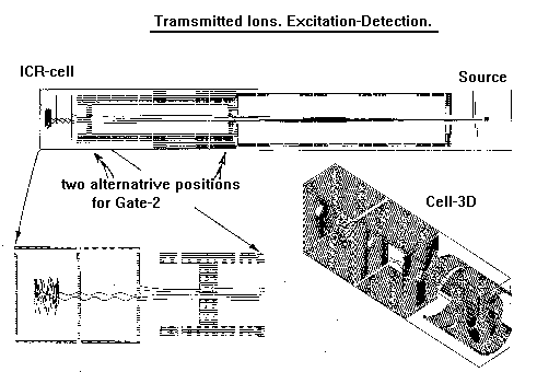
Gate 1 was not used in this example at all as we could control ions time-of-birth. Under the condition of proper setting of the gate 2 (conductance limit position) opening ions are allowed into the cell region and standard excitation-detection sequence follows. Red, blue and green colors in Figure 6 and further correspond to injection, excitation and detection respectively.
The next Figure illustrates the effectiveness of 150 V gate2-locking.
No ions are able to pass the
deceleration even without narrowing the gate following differential aperture.
Simulations carried out using SIMION showed 150 Volts to be appropriate gate- locked voltage at the present position of the second gate. Higher voltages are necessary in regions closer to the cell. 15 Volts deflection at the extraction lens (the first gate) was sufficient to prevent ion propagation into acceleration unit.
TOF and mass resolution predictions were done using the theory above for medium mass/charge ratioof 10^3 amu. Mass resolution of 10^2 is predicted.
Final design places two paired lens elements in the positions marked with the red circles in Fig 1. The first pulse of 1 ęsec applied to the first gate admits ion packet into the flight tube. The puse time before the second gate pulse of 1 usec is applied to gate 2 is adjustable in the range of 1-540 usec. The small diameter of the conductance limit aperture makes it easy to prevent any ions from passing it except during the time when the deflection voltage is set to zero.
Separate electronics problem arose from the necessity of floating the gates at high negative voltages (see the main figure above). Careful measurements to RC constants of the resistive bridges set requirements for floating pulse generators with capacitive isolation. Wave form distortion mainly occurs after the gate is closed.
Gate-open pulse width combined with the length of gate 2 (currently 1 usec across 10 mm) limits resolution of low mas ions (<50). The ions of close masses have enough time to pass through as a packet. In this case resolution is simply t_pulse/t_flight.
Duration lag between gates pulses (currently 1-540 usec) is too short for high masses (>60000). It takes the ion longer then 540 ęsec to travel between the gates.
Resolution of 10^2 is predicted for the mass range of 50-10^3 amu.