The most rigorous descriptions of light matter interactions are provided by quantum electrodynamics (QED), a relativistic field theory in which both the radiation and the material are described quantum mechanically.  Fortunately, this level of rigor is not required for useful descriptions of spectroscopic events. We can base descriptions of spectroscopic events on a semi-classical viewpoint:  material (sample) properties are described quantum mechanically (energy levels defined by wavefunctions) while radiation is viewed classically as waves.  Of course, this demarcation has its limits; it is often convenient to consider light absorbed and emitted by materials quantum mechanically as photons in the semi-classical framework too. 

        In the classical view, EMR traveling (propagating) in a vacuum (free space) is described by wave equations derived from Maxwell’s equations. The wave equations describe the motion of the electric, E, and magnetic, B, fields of EMR:

where c is the speed of light in a vacuum.

        Solutions to these equations are oscillations, hence the name ‘the wave equation’.  The waves are mutually perpendicular electric and magnetic fields, oscillating in planes that are perpendicular to the direction of light propagation. True EMR waves are three dimensional entities, but in this discussion these fields will be represented using their one dimensional counterparts: they are written as

(1.2)

To define terms, ω  is the angular frequency of the field, where ω =ν, ν is the linear frequency, λ is the wavelength of light which is related to ν by λν=c.  The wavevector, k=ω/c=2π/λ, is the spatial analog to the angular frequency.  φ0 represents the initial phase (displacement of wave crest from reference point; zero in the drawing below).  The following drawing shows a wave that has the electric field polarized in the y-direction (oscillates in the y-z plane) and propagates in the z-direction.  The magnetic field (not shown) must be polarized in the x-direction (oscillates in the x-z plane), which comes out of the plane of the page.

        Ordinarily, light rays consist of many waves vibrating in all the directions perpendicular to its direction of propagation (unpolarized).  When the wave oscillates and propagates in a fixed plane (as in Fig. 1A), the light is called plane or linearly polarized.  Polarized light always can be described as a combination of two orthogonal components.  If the light is propagating in a vacuum (free space) or other isotropic three dimensional medium, horizontal (H) and vertical (V) axes are useful references.  When the light is propagating across an interface, the orthogonal components are defined relative to the plane of incidence: s-polarized oscillates in the plane that is perpendicular to plane of incidence and p-polarized oscillates parallel to the plane of incidence.  The phase relationship and relative size of these components (H/V or s/p) define the EMR polarization as shown in Fig. 1B.  If the components have equal lengths (amplitudes) and a phase difference, Δϕ, of 0o or 180 o, the resultant is linearly polarized.  If the components have equal lengths and a phase difference of 90 o or 270 o, the resultant is circularly polarized.  Elliptically polarized light results from other length combinations and/or phase differences. 

Figure 1A: Electric field vector

Figure 1B: Polarizations of EMR

Properties of Light

Radiometric Units

The circumference of a circle of radius r is the perimeter, 2πr.  We can calculate the angle the circle subtends from the ratio of the perimeter to the radius, so the circle subtends an angle of 2πr/r=2π radians.  The radian is technically unitless because both the perimeter and the radius are measured in meters.  Similarly, the surface area covered by a spherical wave at  distance r is 4πr2 (surface of a sphere of radius r).  The solid angle subtended by the sphere is the ratio of the surface to the radius squared, so the sphere subtends 4πr2/r2=4π steradians.  Like the radian, the steradian is technically unitless. The
receptor  also defines a solid angle that intersects that of the source.  If a circular lens is placed a distance d from a source, it collects the light that travels through the solid angle defined by the receptor size and distance: 
where A
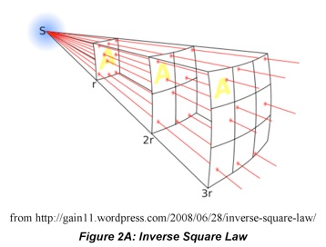
p is the projected area of the receptor.. The projected area is the fraction of the receptor area that can be observed from the source, Acosθ, where θ is the angle of the receptor surface relative to the source.  This means that the amount of light incident on a receiver,                            is inversely proportional to the distance from the source: 
.  This is a famous result called the inverse square law, which is illustrated in Figure 2A. 

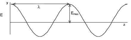
        When radiometric quantities are measured over a specific range of wavelengths or frequencies, spectral units, identified by subscripts λ and ν, respectively, are used.  For example, Bλ is the spectral radiance, the amount of light emitted by an extended source per unit solid angle, per unit projected area, per wavelength range.  For example, a 20W tungsten filament lamp, which emits photons between 300 and 2500nm, will have a spectral radiance around 0.002 Wcm-2nm-1sr-1 if the filament surface area is  1 cm2.  These symbols are easily confused with the amplitudes of the electric and magnetic fields comprising EMR waves.  We will write radiance and irradiance with a fancy font to distinguish them from electric and magnetic fields.


where the E and B are bold indicating that these are vector quantities. Unfortunately, the term intensity (symbol I) is used interchangeably with the irradiance (E), though they are distinct concepts.  Remember, the irradiance refers to radiation incident on a receiver or detector surface; the intensity is light emanating from a point source. 

        Radiometric units also reflect the geometry of the light beam in addition to its source or destination. The amount of light that reaches a detector from a source depends on the solid angle the source subtends (definition below), the source size and power as well as the detector size and distance.  When the output from a source travels in all directions, the solid angle it subtends is 4π sr (the solid angle is the 3D counterpart of the angle, measured in steradians (sr) which are technically unitless) We can understand this by drawing an analogy to a circle. 

        The radiometric system of units describes the radiant energy emitted by a source or striking a receiver.  The basic quantity in this system is radiant energy, Q, in joules (J).  The units do not follow strict SI rules, hence the prominent role of the centimeter (cm).  The Table 1A below lists some of the more common radiometric units. It is important to remember which reference is appropriate for which unit.  Intensity, I, refers to light emanating from point sources, which have infinitely small dimensions.  Light emanating from an extended source, such as a wire or light bulb that has a finite size and surface area, is quantified by its radiance, B.   

        Since optical frequencies are very large, e.g., ~1014 Hz in the visible range, the electric field amplitude is not observed directly.  When light traveling through a medium strikes a detector, such as a photomultiplier tube or your eye, the detector integrates the radiation and the detector registers the signal brightness as the irradiance, E:

(1.3)

Table 1A: Radiometric Units

Adapted from Ingle & Crouch, Spectrochemical Analysis, Prentice-Hall, 1988.

(1.1)

1. EMR Basics